QUICK LINKS
BRIEF OVERVIEW
UNIT I
Purpose of Testing
Dichotomies
Model for Testing
Consequences of Bugs
Taxonomy of Bugs
Summary
UNIT II
Basics of Path Testing
Predicates, Path Predicates and Achievable Paths
Path Sensitizing
Path Instrumentation
Application of Path Testing
Summary
UNIT III
Transaction Flows
Transaction Flow Testing Techniques
Implementation
Basics of Data Flow Testing
Strategies in Data Flow Testing
Application of Data Flow Testing
Summary
UNIT IV
Domains and Paths
Nice and Ugly domains
Domain Testing
Domain and Interface Testing
Domains and Testability
Summary
UNIT V
Path products and Path expression
Reduction Procedure
Applications
Regular Expressions and Flow Anomaly Detection
Summary
UNIT VI
Logic Based Testing
Decision Tables
Path Expressions
KV Charts
Specifications
Summary
|
FLOWGRAPHS AND PATH TESTING:
This unit gives an indepth overview of path testing and its applications.
At the end of this unit, the student will be able to:
- Understand the concept of path testing.
- Identify the components of a control flow diagram and compare the same with a flowchart.
- Represent the control flow graph in the form of a Linked List notation.
- Understand the path testing and selection criteria and their limitations.
- Interpret a control flow-graph and demonstrate the complete path testing to achieve C1+C2.
- Classify the predicates and variables as dependant/independant and correlated/uncorrelated.
- Understand the path sensitizing method and classify whether the path is achievable or not.
- Identify the problem due to co-incidental correctness and choose a path instrumentation method to overcome the problem.
BASICS OF PATH TESTING:
- PATH TESTING:
- Path Testing is the name given to a family of test techniques based on judiciously selecting a set of test paths through the program.
- If the set of paths are properly chosen then we have achieved some measure of test thoroughness. For example, pick enough paths to assure that every source statement has been executed at least once.
- Path testing techniques are the oldest of all structural test techniques.
- Path testing is most applicable to new software for unit testing. It is a structural technique.
- It requires complete knowledge of the program's structure.
- It is most often used by programmers to unit test their own code.
- The effectiveness of path testing rapidly deteriorates as the size of the software aggregate under test increases.
- THE BUG ASSUMPTION:
- The bug assumption for the path testing strategies is that something has gone wrong with the software that makes it take a different path than intended.
- As an example "GOTO X" where "GOTO Y" had been intended.
- Structured programming languages prevent many of the bugs targeted by path testing: as a consequence the effectiveness for path testing for these languages is reduced and for old code in COBOL, ALP, FORTRAN and Basic, the path testing is indespensable.
- CONTROL FLOW GRAPHS:
- The control flow graph is a graphical representation of a program's control structure. It uses the elements named process blocks, decisions, and junctions.
- The flow graph is similar to the earlier flowchart, with which it is not to be confused.
- Flow Graph Elements:A flow graph contains four different types of elements. (1) Process Block (2) Decisions (3) Junctions (4) Case Statements
- Process Block:
- A process block is a sequence of program statements uninterrupted by either decisions or junctions.
- It is a sequence of statements such that if any one of statement of the block is executed, then all statement thereof are executed.
- Formally, a process block is a piece of straight line code of one statement or hundreds of statements.
- A process has one entry and one exit. It can consists of a single statement or instruction, a sequence of statements or instructions, a single entry/exit subroutine, a macro or function call, or a sequence of these.
- Decisions:
- A decision is a program point at which the control flow can diverge.
- Machine language conditional branch and conditional skip instructions are examples of decisions.
- Most of the decisions are two-way but some are three way branches in control flow.
- Case Statements:
- A case statement is a multi-way branch or decisions.
- Examples of case statement are a jump table in assembly language, and the PASCAL case statement.
- From the point of view of test design, there are no differences between Decisions and Case Statements
- Junctions:
- A junction is a point in the program where the control flow can merge.
- Examples of junctions are: the target of a jump or skip instruction in ALP, a label that is a target of GOTO.
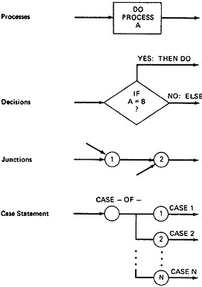
Figure 2.1: Flowgraph Elements
- CONTROL FLOW GRAPHS Vs FLOWCHARTS:
- A program's flow chart resembles a control flow graph.
- In flow graphs, we don't show the details of what is in a process block.
- In flow charts every part of the process block is drawn.
- The flowchart focuses on process steps, where as the flow graph focuses on control flow of the program.
- The act of drawing a control flow graph is a useful tool that can help us clarify the control flow and data flow issues.
- NOTATIONAL EVOULTION:
- The control flow graph is simplified representation of the program's structure.
- The notation changes made in creation of control flow graphs:
- The process boxes weren't really needed. There is an implied process on every line joining junctions and decisions.
- We don't need to know the specifics of the decisions, just the fact that there is a branch.
- The specific target label names aren't important-just the fact that they exist. So we can replace them by simple numbers.
- To understand this, we will go through an example (Figure 2.2) written in a FORTRAN like programming language called Programming Design Language (PDL). The program's corresponding flowchart (Figure 2.3) and flowgraph (Figure 2.4) were also provided below for better understanding.
- The first step in translating the program to a flowchart is shown in Figure 2.3, where we have the typical one-for-one classical flowchart. Note that complexity has increased, clarity has decreased, and that we had to add auxiliary labels (LOOP, XX, and YY), which have no actual program counterpart.
In Figure 2.4 we merged the process steps and replaced them with the single process box. We now have a control flowgraph. But this representation is still too busy. We simplify the notation further to achieve Figure 2.5, where for the first time we can really see what the control flow looks like.
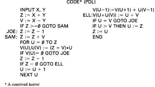
Figure 2.2: Program Example (PDL)
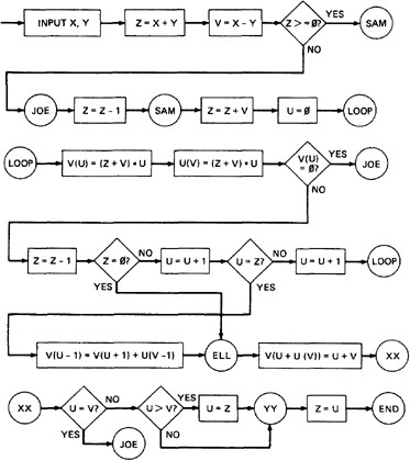
Figure 2.3: One-to-one flowchart for example program in Figure 2.2
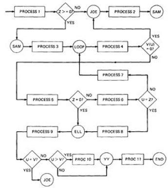
Figure 2.4: Control Flowgraph for example in Figure 2.2
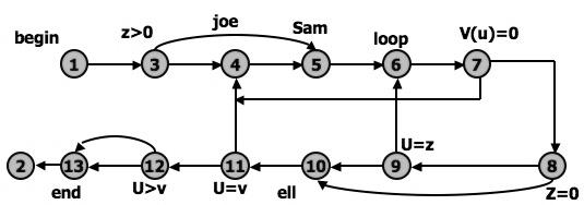
Figure 2.5: Simplified Flowgraph Notation
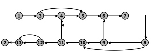
Figure 2.6: Even Simplified Flowgraph Notation
The final transformation is shown in Figure 2.6, where we've dropped the node numbers to achieve an even simpler representation. The way to work with control flowgraphs is to use the simplest possible representation - that is, no more information than you need to correlate back to the source program or PDL.
- LINKED LIST REPRESENTATION:
- Although graphical representations of flowgraphs are revealing, the details of the control flow inside a program they are often inconvenient.
- In linked list representation, each node has a name and there is an entry on the list for each link in the flow graph. only the information pertinent to the control flow is shown.
- Linked List representation of Flow Graph:
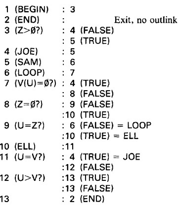
Figure 2.7: Linked List Control Flowgraph Notation
- FLOWGRAPH - PROGRAM CORRESPONDENCE:
- A flow graph is a pictorial representation of a program and not the program itself, just as a topographic map.
- You cant always associate the parts of a program in a unique way with flowgraph parts because many program structures, such as if-then-else constructs, consists of a combination of decisions, junctions, and processes.
- The translation from a flowgraph element to a statement and vice versa is not always unique. (See Figure 2.8)
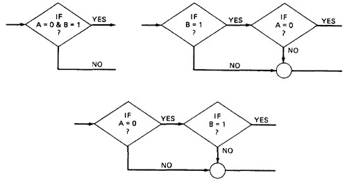
Figure 2.8: Alternative Flowgraphs for same logic (Statement "IF (A=0) AND (B=1) THEN . . .").
- An improper translation from flowgraph to code during coding can lead to bugs, and improper translation during the test design lead to missing test cases and causes undiscovered bugs.
- FLOWGRAPH AND FLOWCHART GENERATION:
- Flowcharts can be
- Handwritten by the programmer.
- Automatically produced by a flowcharting program based on a mechanical analysis of the source code.
- Semi automatically produced by a flow charting program based in part on structural analysis of the source code and in part on directions given by the programmer.
- There are relatively few control flow graph generators.
- PATH TESTING - PATHS, NODES AND LINKS:
- Path:a path through a program is a sequence of instructions or statements that starts at an entry, junction, or decision and ends at another, or possibly the same junction, decision, or exit.
- A path may go through several junctions, processes, or decisions, one or more times.
- Paths consists of segments.
- The segment is a link - a single process that lies between two nodes.
- A path segment is succession of consecutive links that belongs to some path.
- The length of path measured by the number of links in it and not by the number of the instructions or statements executed along that path.
- The name of a path is the name of the nodes along the path.
- FUNDAMENTAL PATH SELECTION CRITERIA:
- There are many paths between the entry and exit of a typical routine.
- Every decision doubles the number of potential paths. And every loop multiplies the number of potential paths by the number of different iteration values possible for the loop.
- Defining complete testing:
- Exercise every path from entry to exit
- Exercise every statement or instruction at least once
- Exercise every branch and case statement, in each direction at least once
- If prescription 1 is followed then 2 and 3 are automatically followed. But it is impractical for most routines. It can be done for the routines that have no loops, in which it is equivalent to 2 and 3 prescriptions.
- EXAMPLE:Here is the correct version.
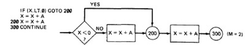
For X negative, the output is X + A, while for X greater than or equal to zero, the output is X + 2A. Following prescription 2 and executing every statement, but not every branch, would not reveal the bug in the following incorrect version:
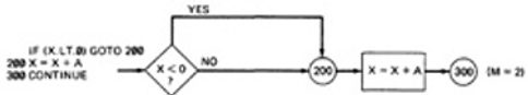
A negative value produces the correct answer. Every statement can be executed, but if the test cases do not force each branch to be taken, the bug can remain hidden. The next example uses a test based on executing each branch but does not force the execution of all statements:
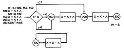
The hidden loop around label 100 is not revealed by tests based on prescription 3 alone because no test forces the execution of statement 100 and the following GOTO statement. Furthermore, label 100 is not flagged by the compiler as an unreferenced label and the subsequent GOTO does not refer to an undefined label.
- A Static Analysis (that is, an analysis based on examining the source code or structure) cannot determine whether a piece of code is or is not reachable. There could be subroutine calls with parameters that are subroutine labels, or in the above example there could be a GOTO that targeted label 100 but could never achieve a value that would send the program to that label.
- Only a Dynamic Analysis (that is, an analysis based on the code's behavior while running - which is to say, to all intents and purposes, testing) can determine whether code is reachable or not and therefore distinguish between the ideal structure we think we have and the actual, buggy structure.
- PATH TESTING CRITERIA:
- Any testing strategy based on paths must at least both exercise every instruction and take branches in all directions.
- A set of tests that does this is not complete in an absolute sense, but it is complete in the sense that anything less must leave something untested.
- So we have explored three different testing criteria or strategies out of a potentially infinite family of strategies.
- Path Testing (Pinf):
- Execute all possible control flow paths through the program: typically, this is restricted to all possible entry/exit paths through the program.
- If we achieve this prescription, we are said to have achieved 100% path coverage. This is the strongest criterion in the path testing strategy family: it is generally impossible to achieve.
- Statement Testing (P1):
- Execute all statements in the program at least once under some test. If we do enough tests to achieve this, we are said to have achieved 100% statement coverage.
- An alternate equivalent characterization is to say that we have achieved 100% node coverage. We denote this by C1.
- This is the weakest criterion in the family: testing less than this for new software is unconscionable (unprincipled or can not be accepted) and should be criminalized.
- Branch Testing (P2):
- Execute enough tests to assure that every branch alternative has been exercised at least once under some test.
- If we do enough tests to achieve this prescription, then we have achieved 100% branch coverage.
- An alternative characterization is to say that we have achieved 100% link coverage.
- For structured software, branch testing and therefore branch coverage strictly includes statement coverage.
- We denote branch coverage by C2.
- Commonsense and Strategies:
- Branch and statement coverage are accepted today as the minimum mandatory testing requirement.
- The question "why not use a judicious sampling of paths?, what is wrong with leaving some code, untested?" is ineffectual in the view of common sense and experience since:
(1.) Not testing a piece of a code leaves a residue of bugs in the program in proportion to the size of the untested code and the probability of bugs.
(2.) The high probability paths are always thoroughly tested if only to demonstrate that the system works properly.
- Which paths to be tested? You must pick enough paths to achieve C1+C2. The question of what is the fewest number of such paths is interesting to the designer of test tools that help
automate the path testing, but it is not crucial to the pragmatic (practical) design of tests. It is better to make many simple paths than a few complicated paths.
- Path Selection Example:
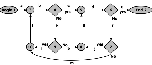
Figure 2.9: An example flowgraph to explain path selection
- Practical Suggestions in Path Testing:
- Draw the control flow graph on a single sheet of paper.
- Make several copies - as many as you will need for coverage (C1+C2) and several more.
- Use a yellow highlighting marker to trace paths. Copy the paths onto a master sheets.
- Continue tracing paths until all lines on the master sheet are covered, indicating that you appear to have achieved C1+C2.
- As you trace the paths, create a table that shows the paths, the coverage status of each process, and each decision.
- The above paths lead to the following table considering Figure 2.9:
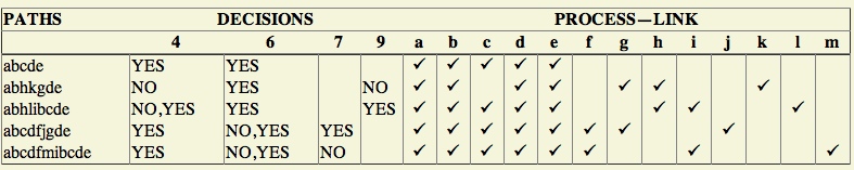
- After you have traced a a covering path set on the master sheet and filled in the table for every path, check the following:
- Does every decision have a YES and a NO in its column? (C2)
- Has every case of all case statements been marked? (C2)
- Is every three - way branch (less, equal, greater) covered? (C2)
- Is every link (process) covered at least once? (C1)
- Revised Path Selection Rules:
- Pick the simplest, functionally sensible entry/exit path.
- Pick additional paths as small variation from previous paths. Pick paths that do not have loops rather than paths that do. Favor short paths that make sense over paths that don't.
- Pick additional paths that have no obvious functional meaning only if it's necessary to provide coverage.
- Be comfortable with your chosen paths. Play your hunches (guesses) and give your intuition free reign as long as you achieve C1+C2.
- Don't follow rules slavishly (blindly) - except for coverage.
- LOOPS:
- Cases for a single loop:A Single loop can be covered with two cases: Looping and Not looping. But, experience shows that many loop-related bugs are not discovered by C1+C2. Bugs hide themselves in corners and congregate at boundaries - in the cases of loops, at or around the minimum or maximum number of times the loop can be iterated. The minimum number of iterations is often zero, but it need not be.
CASE 1: Single loop, Zero minimum, N maximum, No excluded values
- Try bypassing the loop (zero iterations). If you can't, you either have a bug, or zero is not the minimum and you have the wrong case.
- Could the loop-control variable be negative? Could it appear to specify a negative number of iterations? What happens to such a value?
- One pass through the loop.
- Two passes through the loop.
- A typical number of iterations, unless covered by a previous test.
- One less than the maximum number of iterations.
- The maximum number of iterations.
- Attempt one more than the maximum number of iterations. What prevents the loop-control variable from having this value? What will happen with this value if it is forced?
CASE 2: Single loop, Non-zero minimum, No excluded values
- Try one less than the expected minimum. What happens if the loop control variable's value is less than the minimum? What prevents the value from being less than the minimum?
- The minimum number of iterations.
- One more than the minimum number of iterations.
- Once, unless covered by a previous test.
- Twice, unless covered by a previous test.
- A typical value.
- One less than the maximum value.
- The maximum number of iterations.
- Attempt one more than the maximum number of iterations.
CASE 3: Single loops with excluded values
- Treat single loops with excluded values as two sets of tests consisting of loops without excluded values, such as case 1 and 2 above.
- Example, the total range of the loop control variable was 1 to 20, but that values 7,8,9,10 were excluded. The two sets of tests are 1-6 and 11-20.
- The test cases to attempt would be 0,1,2,4,6,7 for the first range and 10,11,15,19,20,21 for the second range.
- Kinds of Loops:There are only three kinds of loops with respect to path testing:
- Nested Loops:
- The number of tests to be performed on nested loops will be the exponent of the tests performed on single loops.
- As we cannot always afford to test all combinations of nested loops' iterations values. Here's a tactic used to discard some of these values:
- Start at the inner most loop. Set all the outer loops to their minimum values.
- Test the minimum, minimum+1, typical, maximum-1 , and maximum for the innermost loop, while holding the outer loops at their minimum iteration parameter values. Expand the tests as required for out of range and excluded values.
- If you've done the outmost loop, GOTO step 5, else move out one loop and set it up as in step 2 with all other loops set to typical values.
- Continue outward in this manner until all loops have been covered.
- Do all the cases for all loops in the nest simultaneously.
- Concatenated Loops:
- Concatenated loops fall between single and nested loops with respect to test cases. Two loops are concatenated if it's possible to reach one after exiting the other while still on a path from entrance to exit.
- If the loops cannot be on the same path, then they are not concatenated and can be treated as individual loops.
- Horrible Loops:
- A horrible loop is a combination of nested loops, the use of code that jumps into and out of loops, intersecting loops, hidden loops, and cross connected loops.
- Makes iteration value selection for test cases an awesome and ugly task, which is another reason such structures should be avoided.
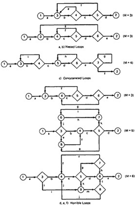
Figure 2.10: Example of Loop types
- Loop Testing TIme:
- Any kind of loop can lead to long testing time, especially if all the extreme value cases are to attempted (Max-1, Max, Max+1).
- This situation is obviously worse for nested and dependent concatenated loops.
- Consider nested loops in which testing the combination of extreme values lead to long test times. Several options to deal with:
- Prove that the combined extreme cases are hypothetically possible, they are not possible in the real world
- Put in limits or checks that prevent the combined extreme cases. Then you have to test the software that implements such safety measures.
PREDICATES, PATH PREDICATES AND ACHIEVABLE PATHS:
- PREDICATE: The logical function evaluated at a decision is called Predicate. The direction taken at a decision depends on the value of decision variable. Some examples are: A>0, x+y>=90.......
- PATH PREDICATE: A predicate associated with a path is called a Path Predicate. For example, "x is greater than zero",
"x+y>=90", "w is either negative or equal to 10 is true" is a sequence of predicates whose truth values will cause the routine to take a specific path.
- MULTIWAY BRANCHES:
- The path taken through a multiway branch such as a computed GOTO's, case statement, or jump tables cannot be directly expressed in TRUE/FALSE terms.
- Although, it is possible to describe such alternatives by using multi valued logic, an expedient (practical approach) is to express multiway branches as an equivalent set of if..then..else statements.
- For example a three way case statement can be written as: If case=1 DO A1 ELSE (IF Case=2 DO A2 ELSE DO A3 ENDIF)ENDIF.
- INPUTS:
- In testing, the word input is not restricted to direct inputs, such as variables in a subroutine call, but includes all data objects referenced by the routine whose values are fixed prior to entering it.
- For example, inputs in a calling sequence, objects in a data structure, values left in registers, or any combination of object types.
- The input for a particular test is mapped as a one dimensional array called as an Input Vector.
- PREDICATE INTERPRETATION:
- The simplest predicate depends only on input variables.
- For example if x1,x2 are inputs, the predicate might be x1+x2>=7, given the values of x1 and x2 the direction taken through the decision is based on the predicate is determined at input time and does not depend on processing.
- Another example, assume a predicate x1+y>=0 that along a path prior to reaching this predicate we had the assignement statement y=x2+7. although our predicate depends on processing,
we can substitute the symbolic expression for y to obtain an equivalent predicate x1+x2+7>=0.
- The act of symbolic substitution of operations along the path in order to express the predicate solely in terms of the input vector is called predicate interpretation.
- Some times the interpretation may depend on the path; for example,
INPUT X
ON X GOTO A, B, C, ...
A: Z := 7 @ GOTO HEM
B: Z := -7 @ GOTO HEM
C: Z := 0 @ GOTO HEM
.........
HEM: DO SOMETHING
.........
HEN: IF Y + Z > 0 GOTO ELL ELSE GOTO EMM
The predicate interpretation at HEN depends on the path we took through the first multiway branch. It yields for the three cases respectively, if Y+7>0, Y-7>0, Y>0.
- The path predicates are the specific form of the predicates of the decisions along the selected path after interpretation.
- INDEPENDENCE OF VARIABLES AND PREDICATES:
- The path predicates take on truth values based on the values of input variables, either directly or indirectly.
- If a variable's value does not change as a result of processing, that variable is independent of the processing.
- If the variable's value can change as a result of the processing, the variable is process dependent.
- A predicate whose truth value can change as a result of the processing is said to be process dependent and one whose truth value does not change as a result of the processing is process independent.
- Process dependence of a predicate does not always follow from dependence of the input variables on which that predicate is based.
- CORRELATION OF VARIABLES AND PREDICATES:
- Two variables are correlated if every combination of their values cannot be independently specified.
- Variables whose values can be specified independently without restriction are called uncorrelated.
- A pair of predicates whose outcomes depend on one or more variables in common are said to be correlated predicates.
For example, the predicate X==Y is followed by another predicate X+Y == 8. If we select X and Y values to satisfy the first predicate, we might have forced the 2nd predicate's truth value to change.
- Every path through a routine is achievable only if all the predicates in that routine are uncorrelated.
- PATH PREDICATE EXPRESSIONS:
- PREDICATE COVERAGE:
- Compound Predicate: Predicates of the form A OR B, A AND B and more complicated boolean expressions are called as compound predicates.
- Some times even a simple predicate becomes compound after interpretation. Example: the predicate if (x=17) whose opposite branch is if x.NE.17 which is equivalent to x>17 . Or. X<17.
- Predicate coverage is being the achieving of all possible combinations of truth values corresponding to the selected path have been explored under some test.
- As achieving the desired direction at a given decision could still hide bugs in the associated predicates.
- TESTING BLINDNESS:
- Testing Blindness is a pathological (harmful) situation in which the desired path is achieved for the wrong reason.
- There are three types of Testing Blindness:
- Assignment Blindness:
- Assignment blindness occurs when the buggy predicate appears to work correctly because the specific value chosen for an assignment statement works with both the correct and incorrect predicate.
- For Example:
| Correct | Buggy |
X = 7
........
if Y > 0 then ... | X = 7
........
if X+Y > 0 then ... |
If the test case sets Y=1 the desired path is taken in either case, but there is still a bug.
- Equality Blindness:
- Equality blindness occurs when the path selected by a prior predicate results in a value that works both for the correct and buggy predicate.
- For Example:
| Correct | Buggy |
if Y = 2 then
........
if X+Y > 3 then ... | if Y = 2 then
........
if X > 1 then ... |
The first predicate if y=2 forces the rest of the path, so that for any positive value of x. the path taken at the second predicate will be the same for the correct and buggy version.
- Self Blindness:
- Self blindness occurs when the buggy predicate is a multiple of the correct predicate and as a result is indistinguishable along that path.
- For Example:
| Correct | Buggy |
X = A
........
if X-1 > 0 then ... | X = A
........
if X+A-2 > 0 then ... |
The assignment (x=a) makes the predicates multiples of each other, so the direction taken is the same for the correct and buggy version.
PATH SENSITIZING:
- REVIEW: ACHIEVABLE AND UNACHIEVABLE PATHS:
- We want to select and test enough paths to achieve a satisfactory notion of test completeness such as C1+C2.
- Extract the programs control flowgraph and select a set of tentative covering paths.
- For any path in that set, interpret the predicates along the path as needed to express them in terms of the input vector. In general individual predicates are compound or may become compound as a result of interpretation.
- Trace the path through, multiplying the individual compound predicates to achieve a boolean expression such as
(A+BC) (D+E) (FGH) (IJ) (K) (l) (L).
- Multiply out the expression to achieve a sum of products form:
ADFGHIJKL+AEFGHIJKL+BCDFGHIJKL+BCEFGHIJKL
- Each product term denotes a set of inequalities that if solved will yield an input vector that will drive the routine along the designated path.
- Solve any one of the inequality sets for the chosen path and you have found a set of input values for the path.
- If you can find a solution, then the path is achievable.
- If you cant find a solution to any of the sets of inequalities, the path is un achievable.
- The act of finding a set of solutions to the path predicate expression is called PATH SENSITIZATION.
- HEURISTIC PROCEDURES FOR SENSITIZING PATHS:
- This is a workable approach, instead of selecting the paths without considering how to sensitize, attempt to choose a covering path set that is easy to sensitize and pick hard to sensitize paths only as you must to achieve coverage.
- Identify all variables that affect the decision.
- Classify the predicates as dependent or independent.
- Start the path selection with un correlated, independent predicates.
- If coverage has not been achieved using independent uncorrelated predicates, extend the path set using correlated predicates.
- If coverage has not been achieved extend the cases to those that involve dependent predicates.
- Last, use correlated, dependent predicates.
PATH INSTRUMENTATION:
- PATH INSTRUMENTATION:
- Path instrumentation is what we have to do to confirm that the outcome was achieved by the intended path.
- Co-incidental Correctness: The coincidental correctness stands for achieving the desired outcome for wrong reason.
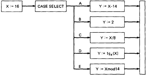
Figure 2.11: Coincidental Correctness
The above figure is an example of a routine that, for the (unfortunately) chosen input value (X = 16), yields the same outcome (Y = 2)
no matter which case we select. Therefore, the tests chosen this way will not tell us whether we have achieved coverage. For example,
the five cases could be totally jumbled and still the outcome would be the same. Path Instrumentation is what we have to do to
confirm that the outcome was achieved by the intended path.
- The types of instrumentation methods include:
- Interpretive Trace Program:
- An interpretive trace program is one that executes every statement in order and records the intermediate values of all calculations, the statement labels traversed etc.
- If we run the tested routine under a trace, then we have all the information we need to confirm the outcome and, furthermore, to confirm that it was achieved by the intended path.
- The trouble with traces is that they give us far more information than we need. In fact, the typical trace program provides so much information that confirming the path from its massive output dump is more work than simulating the computer by hand to confirm the path.
- Traversal Marker or Link Marker:
- A simple and effective form of instrumentation is called a traversal marker or link marker.
- Name every link by a lower case letter.
- Instrument the links so that the link's name is recorded when the link is executed.
- The succession of letters produced in going from the routine's entry to its exit should, if there are no bugs, exactly correspond to the path name.
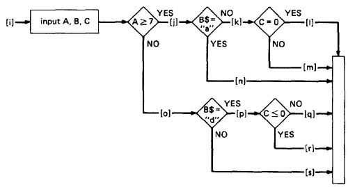
Figure 2.12: Single Link Marker Instrumentation
- Why Single Link Markers aren't enough: Unfortunately, a single link marker may not do the trick because links can be chewed by open bugs.
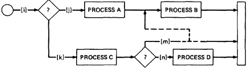
Figure 2.13: Why Single Link Markers aren't enough.
We intended to traverse the ikm path, but because of a rampaging GOTO in the middle of the m link, we go to process B. If coincidental correctness is against us, the outcomes will be the same and we won't know about the bug.
- Two Link Marker Method:
- The solution to the problem of single link marker method is to implement two markers per link: one at the beginning of each link and on at the end.
- The two link markers now specify the path name and confirm both the beginning and end of the link.
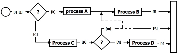
Figure 2.14: Double Link Marker Instrumentation.
Link Counter: A less disruptive (and less informative) instrumentation method is based on counters. Instead of a unique link name to be pushed into a string when the link is traversed, we simply increment a link counter. We now confirm that the path length is as expected. The same problem that led us to double link markers also leads us to double link counters.
APPLICATION OF PATH TESTING:
To be added
SUMMARY:
- Path testing based on structure is a powerful unit-testing tool. With suitable interpretation, it can be used for system functional tests.
- The objective of path testing is to execute enough tests to assure that, as a minimum, C1 + C2 have been achieved.
- Select paths as deviations from the normal paths, starting with the simplest, most familiar, most direct paths from the entry to the exit. Add paths as needed to achieve coverage.
- Add paths to cover extreme cases for loops and combinations of loops: no looping, once, twice, one less than the maximum, the maximum. Attempt forbidden cases.
- Find path-sensitizing input-data sets for each selected path. If a path is unachievable, choose another path that will also achieve coverage. But first ask yourself why seemingly sensible cases lead to unachievable paths.
- Use instrumentation and tools to verify the path and to monitor coverage.
- Incorporate the notion of coverage (especially C2) into all reviews and inspections. Make the ability to achieve C2 a major review agenda item.
- Design test cases and path from the design flowgraph or PDL specification but sensitize paths from the code as part of desk checking. Do covering test case designs either prior to coding or concurrently with coding.
- Document all tests and expected test results as copiously as you would document code. Put test suites under the same degree of configuration control used for the software it tests. Treat each path like a subroutine.
Predict and document the outcome for the stated inputs and the path trace (or name by links). Also document any significant environmental factors and preconditions.
- Your tests must be reproducible so that they can serve a diagnostic purpose if they reveal a bug. An undocumented test cannot be reproduced. Automate test execution.
- Be creatively stupid when conducting tests. Every deviation from the predicted outcome or path must be explained. Every deviation must lead to either a test change, a code change, or a conceptual change.
- A test that reveals a bug has succeeded, not failed.
|